Prepare answers to introductory questions for the lesson.
What is electric current?
What physical quantity best describes the amount of current flowing?
Define a 1 A unit.
What is electric voltage?
Define a 1 V unit.
To measure what quantity we use ammeterammeterammeter and voltmetervoltmetervoltmeter?
Nowadays it is hard to imagine life without electricity. We use various elements through which electric current flows. Some elements of the devices are very large, which is why we often use schematic symbols.
Thanks to this, even a complicated circuit can be presented on a small sheet.
The ability to draw diagrams is important when studying the relationship between the quantities describing the electrical circuit.
What are the schematic designations of various elements of electrical circuits?
R17CCn3zrLtsk
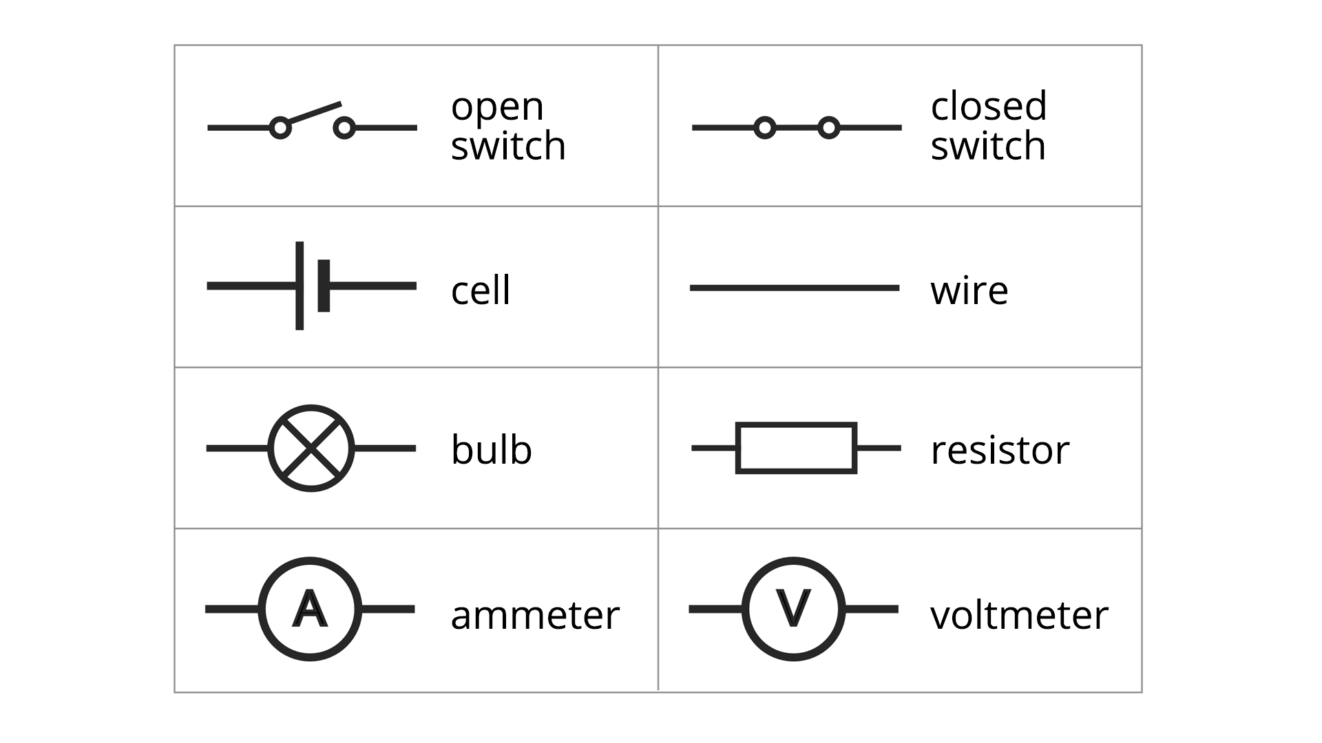
Na rysunku przedstawione są wybrane symbole urządzeń elektrycznych (elementów obwodu). Open switch - pozioma kreska, na której prawym końcu narysowany okrąg, po prawej stronie okręgu ukośna kreska skierowana do góry, obok okrąg, po prawej stronie kreska pozioma. Closed switch - pozioma kreska, na której prawym końcu narysowany okrąg, po prawej stronie okręgu pozioma kreska do okręgu, po jego prawej stronie kreska pozioma. Cell - pozioma kreska, na której prawym końcu pionowa kreska, obok niej krótsza i szersza pionowa kreska, po jej prawej stronie na środku pozioma kreska. Wire - pozioma kreska. Bulb - pozioma kreska, na której prawym końcu okrąg, w środku którego dwie ukośne przecinające się pod kątem prostym kreski, po prawej stronie okręgu pozioma kreska. Resistor - pozioma kreska, na której prawym końcu prostokąt, po jego prawej stronie pozioma kreska. Ammeter - pozioma kreska, na której prawym końcu okrąg, w środku którego duża litera A, po prawej stronie okręgu pozioma kreska. Voltmeter - pozioma kreska, na której prawym końcu okrąg, w środku którego duża litera V, po prawej stronie okręgu pozioma kreska.
Selected symbols of electrical devices (circuit elements)
Source: GroMar, licencja: CC BY 3.0.
RDgnIU1GGsE5m
Pokaz slajdów – elementy obwodu elektrycznego. Instrukcja obsługi z poziomu klawiatury: 1. Uruchomienie aplikacji - ENTER, 2. Na każdym ze slajdów czytany jest automatycznie tekst alternatywny po polsku, 3. Przy pierwszym uruchomieniu na pierwszym slajdzie, czytanie tekstu po angielsku - TAB, 4. Przejście między slajdami: do następnego slajdu - TAB, do poprzedniego slajdu - TAB + SHIFT, 5. Przejście do czytania napisu po angielsku - strzałka w górę + strzałka w dół (czyta tekst po angielsku widoczny na slajdzie).
Pokaz slajdów – elementy obwodu elektrycznego. Instrukcja obsługi z poziomu klawiatury: 1. Uruchomienie aplikacji - ENTER, 2. Na każdym ze slajdów czytany jest automatycznie tekst alternatywny po polsku, 3. Przy pierwszym uruchomieniu na pierwszym slajdzie, czytanie tekstu po angielsku - TAB, 4. Przejście między slajdami: do następnego slajdu - TAB, do poprzedniego slajdu - TAB + SHIFT, 5. Przejście do czytania napisu po angielsku - strzałka w górę + strzałka w dół (czyta tekst po angielsku widoczny na slajdzie).
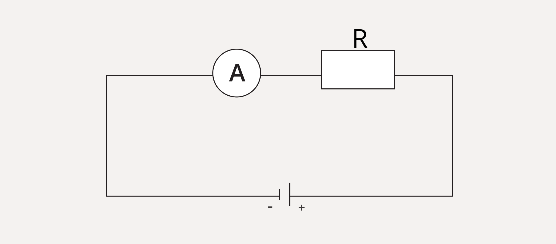
The ammeter must measure the amount of charge that flows through the electrical receiver for one second. It should therefore always be connected in series to the resistor.
R3WAzuSnUDTTt
Rysunek przedstawia schemat układu elektrycznego, prawidłowo podłączony amperomierz (kółko z literą A), szeregowo z opornikiem (prostokąt z literą R). Na obrysie prostokąta, na górnym boku po lewej stronie kółko z literą A, po prawej stronie prostokąt opisany R. Na dolnym boku dwie kreski pionowe, przy krótszej znak minus, przy dłuższej znak plus, symbolizujące źródło napięcia elektrycznego.
Properly connected ammeter - in series with the resistor
Source: GroMar, licencja: CC BY 3.0.
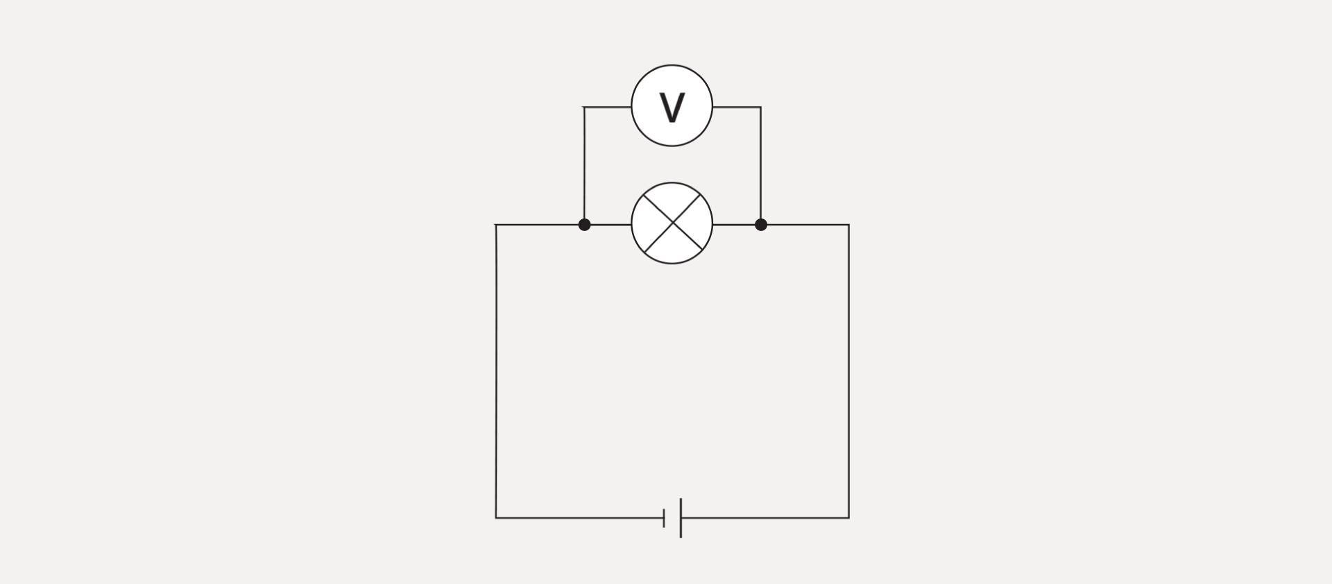
How to connect a voltmetervoltmetervoltmeter correctly?
The voltmeter measures the voltage between two points. The voltmeter's probes must be in contact with these points.
RqTqO5y9qfFJR
Rysunek przedstawia schemat układu elektrycznego, prawidłowo podłączony woltomierz (kółko z literą V) mierzy napięcie na żarówce (kółko z dwoma ukośnymi prostopadłymi kreskami wewnątrz). Woltomierz podłączony równolegle z żarówką - punkty łączenia po dwóch stronach żarówki. Na obrysie prostokąta, na górnym boku kółko symbolizujące żarówkę. Po jego obu stronach punkty, od których narysowane są do góry dwa odcinki pionowe, połączone na końcu odcinkiem poziomym. Na nim narysowane kółka z literą V. Na dolnym boku dwie kreski pionowe, symbolizujące źródło napięcia elektrycznego.
A correctly connected voltmeter measures the voltage across the bulb
Source: GroMar, licencja: CC BY 3.0.
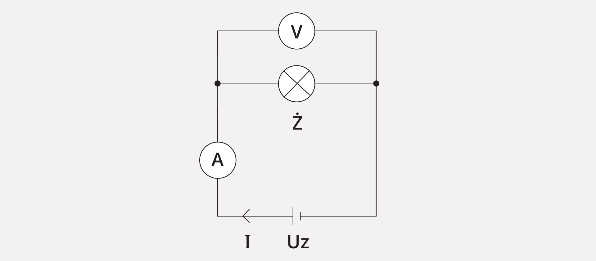
RqG3K3l0LDO6K
Rysunek przedstawia schemat układu elektrycznego, prawidłowo podłączony woltomierz (kółko z literą V) mierzy napięcie na żarówce (kółko z dwoma ukośnymi prostopadłymi kreskami wewnątrz). Woltomierz podłączony równolegle z żarówką - punkty łączenia po dwóch stronach żarówki. Amperomierz (kółko z literą A) połączony między ogniwem Uz a punktem podłączenia woltomierza. Zaznaczono kierunek przepływu prądu I, skierowany od ogniwa w lewo. Na obrysie prostokąta, na górnym boku kółko symbolizujące żarówkę opisane Ż. Po jego obu stronach punkty, od których narysowane są do góry dwa odcinki pionowe, połączone na końcu odcinkiem poziomym. Na nim narysowane kółka z literą V. Na dolnym boku dwie kreski pionowe, symbolizujące źródło napięcia elektrycznego. Na lewym boku kółko z literą A.
In this circuit, the instruments are properly connected. The voltmeter measures the voltage across the bulb and the ammeter measures the current flowing in the circuit
There is a relationship between the voltage applied to the electric current receiver and the current flowing through the conductor.
Instruction
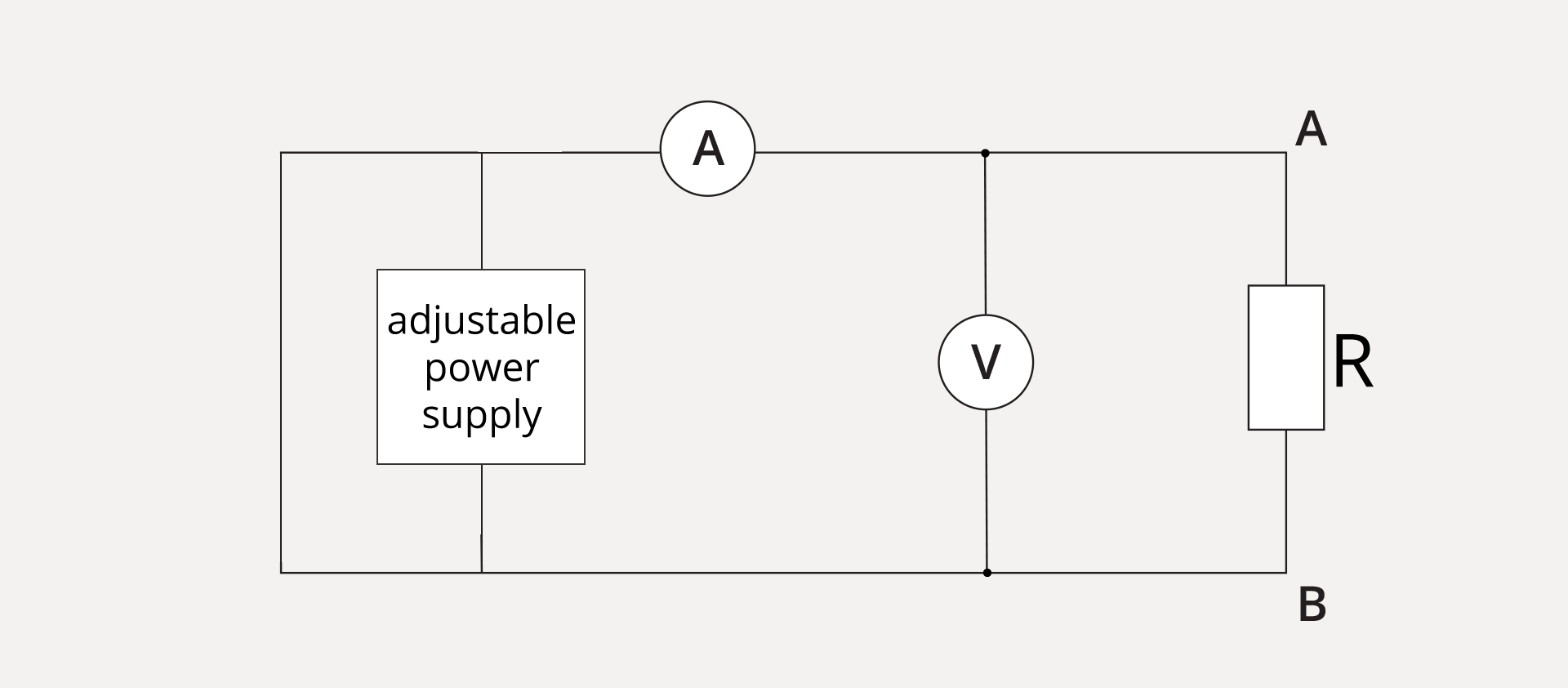
1. Build an electrical circuit as shown in the diagram below.
R1e0ZHEx4fAJc
Rysunek przedstawia schemat układu elektrycznego. Narysowany jest obrys prostokąta. Na jego prawym boku jest prostokąt opisany R symbolizujący opornik. Na rogach prawego boku obwodu oznaczenia A (na górze), B (na dole). Pomiędzy górnym i dolnym bokiem narysowany odcinek pionowy, a na nim kółko z literą V symbolizujące woltomierz, zaznaczono punkty połączenia. Na górnym boku mniej więcej na środku narysowane jest kółko z literą A symbolizujące amperomierz. Blisko lewego boku prostokąta pomiędzy górnym i dolnym bokiem narysowany jest odcinek pionowy. Na nim kwadrat podpisany adjustable power supply symbolizujący zasilacz regulowany.
Electrical circuit
Source: GroMar, licencja: CC BY 3.0.
2. On the power supply, change the supply voltage and read it on a voltmeter.
3. With a given voltage, read out what current flows through the resistor.
4. Record results in the measurement table.
No.
Voltage U (V)
Current I (A)
Notes/conclusions
Elaboration of measurements:
5. Draw a graph of current dependence on the supply voltage.
6. For each measurement, determine the ratio and write it in the table.
7. Compare the results of the and confirm or disprove the research hypothesis.
Electrical circuits are systems of elements (wires, voltage sources, receivers, switches) connected in such a way as to allow the flow of electric current.
AmmeterammeterAmmeter is a device used for measuring the intensity of electric current; it is connected in series to the circuit.
The voltmetervoltmetervoltmeter is a device used to measure the voltage; it is connected in parallel to the circuit.
The current can only flow in closed electrical circuits.
The electrical circuit diagram is a sketch made with the use of graphic symbols, allowing to represent all elements of the electric circuit and their connections.
The intensity of electric current flowing through the receiver is directly proportional to the electrical voltage measured between its ends.
Exercises
RWGUOUlqJXtsf
Exercise 1
Determine which sentences are true. Możliwe odpowiedzi: 1. For each resistor, the I over U ratio is constant., 2. Increasing the voltage applied to the resistor will reduce the current flowing through it., 3. For some resistor, the U over I ratio is constant. In this case, increasing the voltage supplied to the resistor by 10 V will increase the current by 10 A., 4. To measure the current flowing through the resistor, always connect the ammeter in series to it.
Determine which sentences are true. Możliwe odpowiedzi: 1. For each resistor, the I over U ratio is constant., 2. Increasing the voltage applied to the resistor will reduce the current flowing through it., 3. For some resistor, the U over I ratio is constant. In this case, increasing the voltage supplied to the resistor by 10 V will increase the current by 10 A., 4. To measure the current flowing through the resistor, always connect the ammeter in series to it.
Determine which sentences are true.
For each resistor, the ratio is constant.
Increasing the voltage applied to the resistor will reduce the current flowing through it.
For some resistor, the ratio is constant. In this case, increasing the voltage supplied to the resistor by 10 V will increase the current by 10 A.
To measure the current flowing through the resistor, always connect the ammeter in series to it.
zadanie
Source: GroMar, licencja: CC BY 3.0.
Exercise 2
The dependency of the current flowing through the conductor on the voltage applied to this conductor was measured. The measurement data are collected in the table.
No.
Voltage U (V)
Current I (A)
1
1
1
2
2
1,9
3
3
2,7
4
4
3,6
5
5
4,3
6
6
5
7
7
5.8
8
8
5,9
Perform the appropriate calculations and answer the question if the ratio is constant for this conductor. Justify answer.
The ratio is not constant.
Exercise 3
In many electrical circuits, so called nonlinear elements are used. Write in English short information about nonlinear elements of the electrical circuit. Explain also the name of such an element.
R1GGqlTHmPkIR
Exercise 4
Wersja alternatywna ćwiczenia: Match English terms with their Polish equivalents. resistor Możliwe odpowiedzi: 1. włącznik, 2. woltomierz, 3. źródło napięcia, 4. opornik voltage source Możliwe odpowiedzi: 1. włącznik, 2. woltomierz, 3. źródło napięcia, 4. opornik switch Możliwe odpowiedzi: 1. włącznik, 2. woltomierz, 3. źródło napięcia, 4. opornik voltmeter Możliwe odpowiedzi: 1. włącznik, 2. woltomierz, 3. źródło napięcia, 4. opornik
Wersja alternatywna ćwiczenia: Match English terms with their Polish equivalents. resistor Możliwe odpowiedzi: 1. włącznik, 2. woltomierz, 3. źródło napięcia, 4. opornik voltage source Możliwe odpowiedzi: 1. włącznik, 2. woltomierz, 3. źródło napięcia, 4. opornik switch Możliwe odpowiedzi: 1. włącznik, 2. woltomierz, 3. źródło napięcia, 4. opornik voltmeter Możliwe odpowiedzi: 1. włącznik, 2. woltomierz, 3. źródło napięcia, 4. opornik
Match English terms with their Polish equivalents.
włącznik, źródło napięcia, woltomierz, opornik
resistor
voltage source
switch
voltmeter
R14xVddr2ltRk1
Interaktywna gra, polegająca na łączeniu wyrazów w pary w ciągu jednej minuty. Czas zaczyna upływać wraz z rozpoczęciem gry. Jeden ruch to odkrywanie najpierw jednej potem drugiej karty z wyrazem. Każdy wyraz jest odczytywany. Kolejny ruch to odkrywanie trzeciej i czwartej karty. W ten sposób odsłuchasz wszystkie wyrazy. Nawigacja z poziomu klawiatury za pomocą strzałek, odsłuchiwanie wyrazów enterem lub spacją. Znajdź wszystkie pary wyrazów.
Interaktywna gra, polegająca na łączeniu wyrazów w pary w ciągu jednej minuty. Czas zaczyna upływać wraz z rozpoczęciem gry. Jeden ruch to odkrywanie najpierw jednej potem drugiej karty z wyrazem. Każdy wyraz jest odczytywany. Kolejny ruch to odkrywanie trzeciej i czwartej karty. W ten sposób odsłuchasz wszystkie wyrazy. Nawigacja z poziomu klawiatury za pomocą strzałek, odsłuchiwanie wyrazów enterem lub spacją. Znajdź wszystkie pary wyrazów.
Match Polish terms with their English equivalents.
voltmeter
switch
voltage source
włącznik
resistor
źródło napięciowe
opornik
ammeter
woltomierz
amperomierz
Source: Zespół autorski Politechniki Łódzkiej, licencja: CC BY 3.0.