What is voltage and what kind of device do we use to measure it?
What is the current intensity and what kind of device do we use to measure it?
Define the electrical resistance.
How do we connect a ammeterammeterammeter in the electric circuit?
How do we connect a voltmetervoltmetervoltmeter in the electric circuit?
R1Ed9MaBX96PZ
Na ilustracji interaktywnej znajduje się układ elektryczny. Zasilacz stałoprądowy (wejście plus), oznaczony numerem 1, podłączony jest do włącznika, oznaczonego numerem 2. Włącznik połączony jest z opornikiem, oznaczonym numerem 4, w tym samym miejscu podłączony do opornika jest woltomierz (wejście minus), oznaczony numerem 3, wskazujący 4,5221 woltów. Opornik po drugiej stronie połączony jest do wejścia plus woltomierza oraz do żarówki. Żarówka podłączona jest także do wejścia plus amperomierza, oznaczonego numerem 5, wskazującego 0,487696 amperów. Amperomierz od wejścia minus połączony jest z zasilaczem. Na numerach widoczne są podpisy. 1. zasilacz stałoprądowy - DC power supply {audio}, 2. włącznik - switch {audio}, 3. woltomierz - voltmeter {audio}, 4. opornik - resistor {audio}, 5. amperomierz - ammeter {audio}.
Na ilustracji interaktywnej znajduje się układ elektryczny. Zasilacz stałoprądowy (wejście plus), oznaczony numerem 1, podłączony jest do włącznika, oznaczonego numerem 2. Włącznik połączony jest z opornikiem, oznaczonym numerem 4, w tym samym miejscu podłączony do opornika jest woltomierz (wejście minus), oznaczony numerem 3, wskazujący 4,5221 woltów. Opornik po drugiej stronie połączony jest do wejścia plus woltomierza oraz do żarówki. Żarówka podłączona jest także do wejścia plus amperomierza, oznaczonego numerem 5, wskazującego 0,487696 amperów. Amperomierz od wejścia minus połączony jest z zasilaczem. Na numerach widoczne są podpisy. 1. zasilacz stałoprądowy - DC power supply {audio}, 2. włącznik - switch {audio}, 3. woltomierz - voltmeter {audio}, 4. opornik - resistor {audio}, 5. amperomierz - ammeter {audio}.
A typical experimental circuit used to determine resistance of a resistor and power dissipated on it
Determination of the value of electrical resistanceresistanceresistance and dissipated powerpowerpower using an ammeterammeterammeter and a voltmetervoltmetervoltmeter.
Using an ammeterammeterammeter and a voltmetervoltmetervoltmeter, you can determine the resistor resistanceresistanceresistance and the powerpowerpower dissipated on it with acceptable accuracy.
Instruction
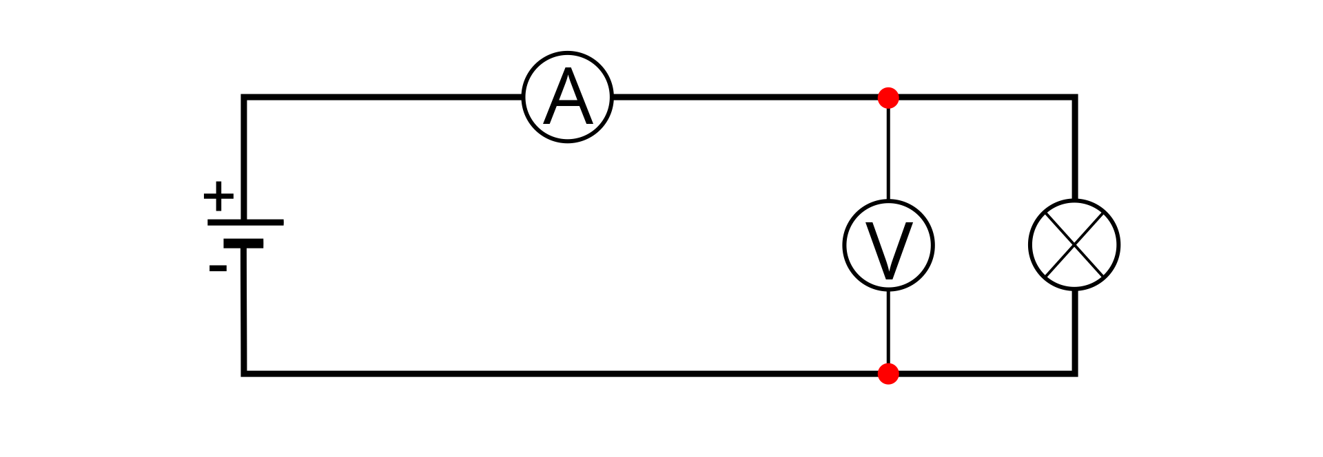
1. Build the experimental circuit according to the diagram:
R5bvjhOXMaCRA
Ilustracja przedstawia schemat obwodu elektrycznego. Na obrysie prostokąta, na górnym boku po lewej stronie kółko z literą A, na prawym boku kółko z dwoma odcinkami prostopadłymi wewnątrz, na lewym boku źródło zasilania (od dołu krótka kreska pozioma opisana minus, puste miejsce, dłuższa kreska pozioma opisana plus). Po prawej stronie na górnym i dolnym boku punkty, między nimi linia pionowa łączą je, na niej kółko z V.
Circuit
Source: GroMar, licencja: CC BY 3.0.
2. Measure the current in the circuit using an ammeter. 3. Measure the voltage on the resistor using a voltmeter. 4. Change the battery supplying the circuit to another one and repeat the measurements. 5. Write down the results in the measurementmeasurementmeasurement table.
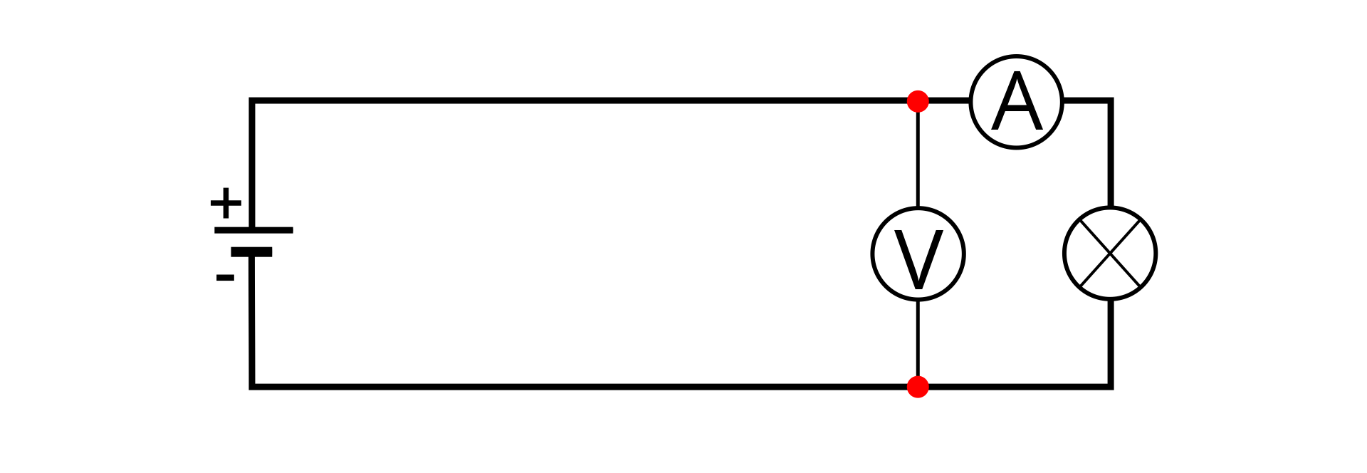
6. Repeat steps 1 to 5 for the circuit built according to the diagram below.
R1PZLWTl2oSI21
Ilustracja przedstawia schemat obwodu elektrycznego. Na obrysie prostokąta, na górnym boku po prawej stronie kółko z literą A, na prawym boku kółko z dwoma odcinkami prostopadłymi wewnątrz, na lewym boku źródło zasilania (od dołu krótka kreska pozioma opisana minus, puste miejsce, dłuższa kreska pozioma opisana plus). Po lewej stronie na górnym i dolnym boku punkty, między nimi linia pionowa łączą je, na niej kółko z V.
1. Based on the measurements made, determine for both measurementmeasurementmeasurement tables the resistanceresistanceresistance and the powerpowerpower dissipated on the resistor.
Comments
If the measurements were performed correctly, the results for the measurement table No. 1 and No. 2 differ.
Differences arise from the fact that both an ammeterammeterammeter and a voltmetervoltmetervoltmeter are not ideal devices.
The results of measurements are influenced by the internal resistance of the measuring instruments.
2. Determine the average value of the resistanceresistanceresistance and the power dissipated on it on the basis of all measurements both from the measurementmeasurementmeasurement table No. 1 and No. 2.
3. Determine the lowest and the largest values of the resistance based on all measurements from both measurement table No. 1 and No. 2.
4. Determine the uncertainty of from the formula
5. Proceeding in the same way as in the case of resistance, determine the uncertainty of the average powerpowerpower .
6. Write down correctly the resistance measurement result together with measurement uncertainty.
7. Write down correctly the power measurement result together with measurement uncertainty.
Summary
To determine the electrical resistance and resistor power, you must build an electrical circuit consisting of: electrical wires, battery, resistor, ammeter and voltmeter.
Then measure voltage and current.
Based on the experimental results, you determine resistanceresistanceresistance and powerpowerpower.
Exercises
R3LaP4GWVHDbR
Exercise 1
Wersja alternatywna ćwiczenia: Determine which sentence is true. Możliwe odpowiedzi: 1. A very good ammeter has very little internal resistance. , 2. A very good voltmeter has very little internal resistance. , 3. Connecting the voltmeter in series into the electrical circuit will destroy it. , 4. In a correctly assembled system, the ammeter and voltmeter are connected in series to the electric circuit.
Wersja alternatywna ćwiczenia: Determine which sentence is true. Możliwe odpowiedzi: 1. A very good ammeter has very little internal resistance. , 2. A very good voltmeter has very little internal resistance. , 3. Connecting the voltmeter in series into the electrical circuit will destroy it. , 4. In a correctly assembled system, the ammeter and voltmeter are connected in series to the electric circuit.
Determine which sentence is true.
A very good ammeter has very little internal resistance.
A very good voltmeter has very little internal resistance.
Connecting the voltmeter in series into the electrical circuit will destroy it.
In a correctly assembled system, the ammeter and voltmeter are connected in series to the electric circuit.
zadanie
Source: GroMar, licencja: CC BY 3.0.
Exercise 2
Use interactive illustration „A typical experimental circuit used to determine resistance of a resistor and power dissipated on it” and determine the resistance of the bulb.
About 11 Ω.
Exercise 3
Write in English a short note about the Wheatstone bridge. Find information on it on the Internet. Draw a diagram of such a bridge and show what it is for.
RE41GDtcT17gn
Exercise 4
Wersja alternatywna ćwiczenia: Indicate which pairs of expressions or words are translated correctly. Możliwe odpowiedzi: 1. pomiar - measurement, 2. amperomierz - voltmeter, 3. opór - resistance, 4. moc - power, 5. woltomierz - ammeter
Wersja alternatywna ćwiczenia: Indicate which pairs of expressions or words are translated correctly. Możliwe odpowiedzi: 1. pomiar - measurement, 2. amperomierz - voltmeter, 3. opór - resistance, 4. moc - power, 5. woltomierz - ammeter
Indicate which pairs of expressions or words are translated correctly.
pomiar - measurement
amperomierz - voltmeter
opór - resistance
moc - power
woltomierz - ammeter
zadanie
Source: GroMar, licencja: CC BY 3.0.
R3kaQff3swim61
Interaktywna gra, polegająca na łączeniu wyrazów w pary w ciągu jednej minuty. Czas zaczyna upływać wraz z rozpoczęciem gry. Jeden ruch to odkrywanie najpierw jednej potem drugiej karty z wyrazem. Każdy wyraz jest odczytywany. Kolejny ruch to odkrywanie trzeciej i czwartej karty. W ten sposób odsłuchasz wszystkie wyrazy. Nawigacja z poziomu klawiatury za pomocą strzałek, odsłuchiwanie wyrazów enterem lub spacją. Znajdź wszystkie pary wyrazów.
Interaktywna gra, polegająca na łączeniu wyrazów w pary w ciągu jednej minuty. Czas zaczyna upływać wraz z rozpoczęciem gry. Jeden ruch to odkrywanie najpierw jednej potem drugiej karty z wyrazem. Każdy wyraz jest odczytywany. Kolejny ruch to odkrywanie trzeciej i czwartej karty. W ten sposób odsłuchasz wszystkie wyrazy. Nawigacja z poziomu klawiatury za pomocą strzałek, odsłuchiwanie wyrazów enterem lub spacją. Znajdź wszystkie pary wyrazów.
Match Polish terms with their English equivalents.
resistance
voltmeter
power
moc
opór
measurement
woltomierz
amperomierz
ammeter
pomiar
Source: Zespół autorski Politechniki Łódzkiej, licencja: CC BY 3.0.